Draw Circle Radius 1 Latex
Introduction
TikZ is probably the most complex and powerful tool to create graphic elements in LaTeastTen. Starting with a simple case, this commodity introduces some bones concepts: drawing lines, dots, curves, circles, rectangles etc.
Firstly, load the tikz bundle past including the line \usepackage{tikz} in the preamble of your document, so draw a graphic using the tikzpicture environment.
\documentclass {article} \usepackage {tikz} \begin {document} \begin {tikzpicture} \draw [gray, thick] (-1,2) -- (2,-4); \depict [gray, thick] (-1,-1) -- (two,2); \filldraw [black] (0,0) circle (2pt) node[anchor=west]{Intersection point}; \end {tikzpicture} \end {certificate}
Open this example in Overleaf
This example produces the following output:
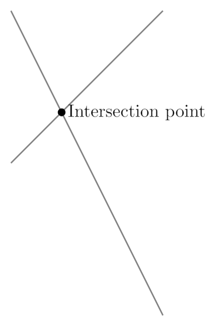
In this case two lines and i point are drawn. To add a line the command \depict[gray, thick] defines a graphic element whose colour is grey and with a thick stroke. The line is actually defined by it'southward two endpoints, (-1,two) and (2,-four), joined by --.
The point is actually a circle drawn by \filldraw[black], this command will not merely draw the circle just fill it using blackness. In this command the centre indicate (0,0) and the radius (2pt) are declared. Next to the signal is a node, which is actually a box containing the text intersection point, and anchored at the west of the point.
Information technology'due south important to notice the semicolon ; used at the end of each draw command.
Note: The tikzfigure environment can be enclosed inside a figure or similar environment. Meet the Inserting Images commodity for more data on this topic.
Basic elements: points, lines and paths
In this department we provide some examples showing how to create some basic graphic elements which tin can exist combined to create more elaborate figures.
\documentclass {article} \usepackage {tikz} \begin {document} \begin {tikzpicture} \depict (-2,0) -- (two,0); \filldraw [greyness] (0,0) circumvolve (2pt); \describe (-2,-2) .. controls (0,0) .. (2,-2); \draw (-ii,2) .. controls (-1,0) and (one,0) .. (two,two); \stop {tikzpicture} \end {document}
Open this example in Overleaf
This example produces the following output:
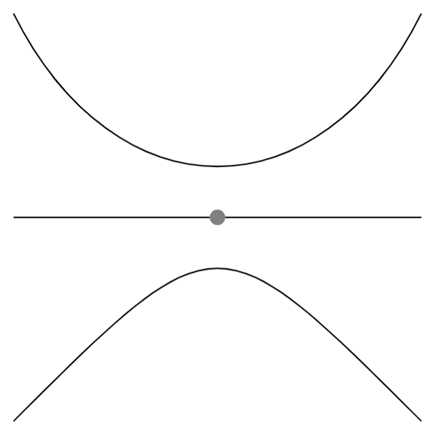
There are three bones commands in this example:
-
\draw (-2,0) -- (ii,0);: This defines a line whose endpoint are(-2,0)and(2,0). -
\filldraw [gray] (0,0) circumvolve (2pt);: The bespeak is created as a very smallgraycirclecentred at(0,0)and whose radius is(2pt). The\filldrawcommand is used to draw elements and fill them with a specific colour. See the next department for more examples. -
\draw (-2,two) .. controls (-1,0) and (one,0) .. (2,ii);: Draws a Bézier curve. At that place are 4 points defining information technology:(-ii,ii)and(2,ii)are its endpoints,(-1,0)and(one,0)are control points that determine "how curved" it is. You can think of these two points as "attractor points".
Basic geometric shapes: Circles, ellipses and polygons
Geometric figures can be synthetic from simpler elements and then let's start with circles, ellipses and arcs.
\documentclass {article} \usepackage {tikz} \brainstorm {certificate} \begin {tikzpicture} \filldraw [color=red!60, make full=red!5, very thick](-1,0) circle (1.five); \fill [blue!50] (2.5,0) ellipse (i.five and 0.v); \depict [ultra thick, ->] (six.v,0) arc (0:220:i); \end {tikzpicture} \terminate {document}
Open this example in Overleaf
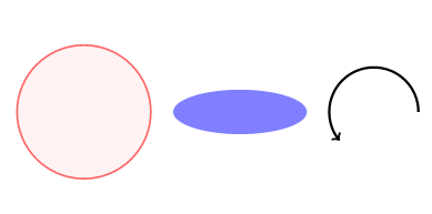
This case produces the following output:
-
\filldraw[color=red!threescore, fill=red!5, very thick](-one,0) circle (1.5);: This command was used in the previous department to depict a point, just in this instance at that place are some additional parameters inside the brackets. These are explained below:-
color=red!lx: The colour of the ring around the circle is set to 60% red (lighter than "pure" red). Come across the reference guide for a list of the default colours bachelor in LaTeX; besides, see Using colours in LaTeX to learn how to create your ain colours. -
fill up=blood-red!v: The circle is filled with an fifty-fifty lighter shade of ruby. -
very thick: This parameter defines the thickness of the stroke. Meet the reference guide for a consummate list of values.
-
-
\make full[blue!50] (ii.five,0) ellipse (1.v and 0.5);: To create an ellipse you provide a centre point(ii.5,0), and two radii: horizontal and vertical (ane.5and0.5respectively). Also notice the commandfillinstead ofdescribeor filldraw, this is because, in this example, there'south no need to control outer and inner colours. -
\draw[ultra thick, ->] (6.5,0) arc (0:220:1);: This command volition describe an arc starting at(6.5,0). The extra parameter->indicates that the arc will have an pointer at the end. In addition to the starting betoken you must provide three boosted values: the starting and catastrophe angles, and the radius; hither, these 3 parameter values are provided in the format(0:220:1).
In addition to curved geometric shapes you tin can also create elements that use straight lines, using a similar syntax:
\documentclass {article} \usepackage {tikz} \begin {document} \begin {tikzpicture} \draw [bluish, very thick] (0,0) rectangle (3,2); \draw [orangish, ultra thick] (4,0) -- (half-dozen,0) -- (5.7,2) -- cycle; \end {tikzpicture} \terminate {document}
Open this example in Overleaf
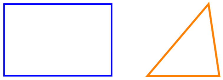
This example produces the following output:
-
\draw[blue, very thick] (0,0) rectangle (3,2);: Rectangles are created by the special commandrectangle. Yous take to provide 2 points, the first one is where the "pencil" begins to draw the rectangle and the second 1 is the diagonally opposite corner point. -
\draw[orange, ultra thick] (4,0) -- (half dozen,0) -- (five.vii,2) -- cycle;: To draw a polygon we describe a closed path of straight lines: a line from(four,0)to(vi,0)and a line from(six,0)to(five.7,ii). Thebicycledidactics means that the outset and end points should coincide to create a "closed" path (shape), which results in construction of the final line segment.
Diagrams
Nodes are probably the most versatile elements in TikZ. We've already used 1 node in the introduction—to add some text to the effigy. The adjacent case uses nodes to create a diagram.
\documentclass {article} \usepackage {tikz} \usetikzlibrary {positioning} \begin {document} \brainstorm {tikzpicture}[ roundnode/.mode={circle, describe=greenish!lx, fill up=green!five, very thick, minimum size=7mm}, squarednode/.fashion={rectangle, draw=red!60, fill up=red!v, very thick, minimum size=5mm}, ] %Nodes \node [squarednode] (maintopic) {2}; \node [roundnode] (uppercircle) [above=of maintopic] {1}; \node [squarednode] (rightsquare) [correct=of maintopic] {3}; \node [roundnode] (lowercircle) [beneath=of maintopic] {four}; %Lines \draw [->] (uppercircle.due south) -- (maintopic.north); \draw [->] (maintopic.east) -- (rightsquare.westward); \draw [->] (rightsquare.south) .. controls +(down:7mm) and +(correct:7mm) .. (lowercircle.east); \end {tikzpicture} \end {document}
Open this example in Overleaf
This example produces the post-obit output:
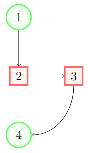
There are essentially three commands in this figure: A node definition, a node announcement and lines that join two nodes.
-
roundnode/.mode={circle, depict=dark-green!60, fill=light-green!5, very thick, minimum size=7mm}: Passed every bit a parameter to thetikzpictureenvironment. It defines a node that will exist referenced asroundnode: this node will be a circle whose outer ring will be drawn using the colourgreen!lxand volition be filled usinggreen!five. The stroke volition bevery thickand itsminimum sizeis7mm. The line beneath this defines a second rectangle-shaped node calledsquarednode, using similar parameters. -
\node[squarednode] (maintopic) {2};: This will create asquarednode, equally defined in the previous command. This node will have an id ofmaintopicand will contain the numberii. If you leave an empty infinite inside the braces no text volition be displayed. -
[above=of maintopic]: Notice that all only the first node accept an boosted parameter that determines its position relative to other nodes. For instance,[in a higher place=of maintopic]means that this node should announced above the node namedmaintopic. For this positioning system to work you have to add\usetikzlibrary{positioning}to your preamble. Without thepositioninglibrary, you can employ the syntaxabove of=maintopicinstead, just thepositioningsyntax is more than flexible and powerful: you can extend it to writeabove=3cm of maintopici.e. control the actual altitude frommaintopic. -
\draw[->] (uppercircle.south) -- (maintopic.north);: An arrow-similar direct line will be drawn. The syntax has been already explained in the bones elements section. The only difference is the manner in which we write the endpoints of the line: by referencing a node (this is why we named them) and a position relative to the node.
Reference Guide
Possible color and thickness parameters in the tikz bundle:
| parameter | values | picture |
|---|---|---|
| color | white, black, cerise, green, blue, cyan, magenta, yellow | 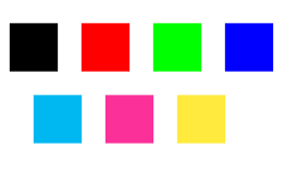 |
| thickness | ultra sparse, very sparse, thin, thick, very thick, ultra thick | 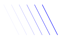 |
More colours may exist available in your LaTeX distribution. See Using colours in LaTeX
Further reading
For more data see:
- Using colours in LaTeX
- Pgfplots package
- Inserting Images
- Lists of tables and figures
- Positioning images and tables
- Drawing diagrams direct in LaTeX
- The TikZ and PGF Packages Manual
- TikZ and PGF examples at TeXample.net
Source: https://www.overleaf.com/learn/latex/TikZ_package
0 Response to "Draw Circle Radius 1 Latex"
Post a Comment